
Description
| SETTINGS | UNIT | UNIT |
|---|---|---|
| Round cutting capacity | mm | 325 |
| Flat cutting capacity | mm | 350 x 325 |
| Square cutting capacity | mm | 325 |
| Main drive motor | kW | 3 |
| Hydraulic pump | kW | 0,55 |
| Power motor | kW | 0,25 |
| Coolant pump | kW | 0,12 |
| Cutting speeds | m/min. | 20 – 100 |
| Bracelet dimensions | mm | 4160x34x1.1 |
| Working height | mm | 580 |
| Weight | kg | 1030 |
| Length | mm | 2450 |
| Width | mm | 900 |
| Height | mm | 1500 |
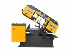
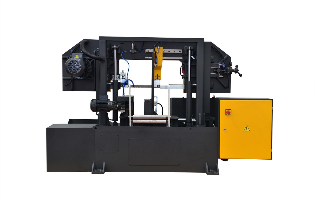
Made entirely of steel.
The rear jaw contains a number of hardened rollers driven by a worm gear and a wheel by an electric motor.
The front vise consists of a number of free rollers.
A limit switch mounted on the vise stops the machine when the block is exhausted.
Once the workpiece is clamped between the rollers, no further tightening is necessary.
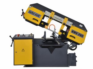
The workpiece is conveyed through the vise to the bar stop which contains a micro-switch controlling the bar feed motor.
A parts counter controls the number of cuts.
The machines stop automatically when the blade breaks.
The machines are equipped with a removable coolant reservoir incorporating an electric submerged coolant pump that supplies coolant to both guide assemblies.
The bi-metal saw blade and 1.2 meter feed roller table are supplied as standard.
- Chip conveyor
- 3Mt Material Roller Table
- Hydraulic blade tension
- ILC microspray device
- Saw blade 34
- Mobile arm/vise
- Inverter
- Safety switch
- Hydromechanical blade tension
- Saw blade brash
- line path
- Metarian boundary tree
- Hydraulic vice
- Control Panel
- Mechanical upper clamping
- Robust gearbox
- Optical height adjustment
- Pressure adjustment
- Coolant pump
- 1.2 m roller table